Technical Specifications:
USB: USB 1.1 and 2.0 compatible
Power consumption: USB side - less than 100mA
Transceiver side less than 200mA at 13.5V (max. 16V)
Radio Port: RxD, TxD, max. 57,600 Baud
- levels: TTL, inverted TTL, open collector bus, RS232
CW: open collector, max 30V/400mA
FSK: open collector, max 30V/400mA
- supported 5/6/7/8bit data length, 1/1.5/2 stop bit, up to 300
Baud
PTT: open collector, max 30V/100mA
PA PTT: selectable by jumper
- open collector, max. 48V/1.5A
- relay contact, max. 125VAC/2A 60VDC/2A
LNA PTT: selectable by jumper
- open collector, max. 48V/1.5A
- relay contact, max. 125VAC/2A 60VDC/2A
Audio Out:
- single channel (left)
- output impedance:600 Ohm
- output level: 4V p-p (max)
- AC coupled
- 3dB bandwidth: 0.2 - 6KHz typical
- Sampling rates: 32000, 44100, and 48000 Hz
Audio In:
- dual channel (stereo)
- input impedance: 50k Ohm
- input level: 4V p-p (max)
- AC coupled
- 3dB bandwidth: 0.2 - 6KHz typical
- Sampling rates: 8000, 11025, 16000, 22050, 32000, 44100, and 48000 Hz
Dimensions:
W 165mm (6.5") x H 44mm (1.75") x D
110mm (4.38")
Weight: 1100g (2.4 lbs.)
Requirements:
Minimum - 800 MHz IBM PC compatible computer with Windows XP, 256 MB RAM, CD-ROM, USB1.1 port, Transceiver, logger or control software (any).
Recommended - 2 GHz PC with Windows XP or higher, 512MB RAM, CD-ROM, USB2.0 port,
Transceiver with computer port, logger or control software (any)
Also Supported - Apple G4 or better and OS 10.3 or
later with MacLoggerDX
from Dog Park
Software, Ltd.
Note: Windows 98 (all versions) and Windows 2000 are no longer supported.
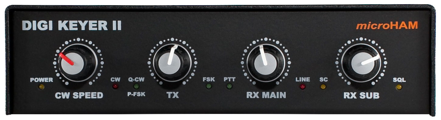
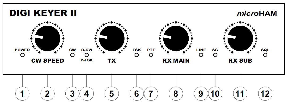
Front panel
1 - Power
Indicates when interface is
receiving power
2 - CW Speed
WinKey speed control
3 - CW
LED flashes when CW
output is active.
4 - Q-CW/P-FSK
LED flashes with
right channel audio On/Off keying
5 - TX
Transmit
audio level
6 - FSK
LED blinks with FSK
outupt (On indicates "closed" regardless of polarity)
7 - PTT
LED lights when PTT
is active.
8 - RX Main
Adjusts
main receiver audio level (left channel)
9 - Line
LED
lights when sound card Line input is active
10 - SC
LED flashes when
application opens sound card for output.
11 - RX Sub
Adjusts
sub receiver audio level (right channel)
12 - SQL
LED
indicates transceiver squelch status (where available)
Rear panel
1 - Radio
DB15F
connector for radio interface.
2 - u2R Mic
3.5mm jack
for microphone input from micro2R
only.
3 - RADIO
USB B
connector for computer connection.
4 - Sub Rx
3.5 mm
connector for audio from a second receiver.
5 - USB
MiniDIN-6 for
a PS/2 Keyboard or keypad, FH-2 style keypad or CI-V output.
6 - PTT IN
RCA for transceiver PTT output
(amplifier PTT)
7 - PA PTT
PTT output for amplifier
8 - Ground
Terminal for ground lug
9 - u2R Out
3.5mm jack for output to micro2R
only.
10 - Paddle
6.3mm
(1/4") stereo jack for keyer paddles (tip is left paddle).
11 - FOOTSW
Optional foot switch or hand PTT
input.
12 - LNA PTT
PTT output for bypassing
a Low Noise
Amplifier (Receiver preamplifier).
Copyright
� 2010
- microHAM America, LLC
webmaster: W4TV